RGBW Mechanical Keyboard
Designing a custom mechanical keyboard from the ground up.
RGBW Mechanical Keyboard
Overview
Designing a custom mechanical keyboard from the ground up.
Project Overview
This project was an attempt to solve a real world problem. I wanted a mechanical keyboard with a 65% compact, in-line layout, hot-swap mechanical switches, and most importantly, backlit with RGB-W LEDs
Key Features
KEY Features
- RGBW LEDs: RGB LEDs with a dedicated W channel for white. Cool, neutral, and warm white are all considered.
- Hot-Swappable Key Switches: Easily swap the key switches for personal preference.
- Compact 80%: Compact 10-keyless design.
The Prototype
- Size: 8 Keys total in a 2x4 design
- Daisy chainable: Ability to connect numerous PCBs as one.
- Secondary Layer: Ability to connect a secondary PCB below the primary PCB to test LEDs with different key switches
- I/O: Connect to any MCU for development.
Technical Specifications
| Specification | Value |
|---|---|
| Microcontroller | Arduino Uno R3 (ATmega328P) |
| Operating Voltage | 5V |
| Weight | 485g |
| Dimensions | 18cm x 12cm x 8cm |
Prototype Analysis
Performance Results
,After extensive testing and PID tuning, the robot achieved:
- Line Following Accuracy: 95% on standard tracks
- Maximum Track Speed: Successfully follows lines at 80cm/s
- Curve Handling: Navigates 90° turns without losing the line
- Obstacle Response: Stops within 10cm of detected obstacles
Lessons Learned
- PID Tuning: Start with proportional control only, then add integral and derivative terms
- Sensor Calibration: Regular calibration is crucial for consistent performance
- Power Management: Use voltage regulators for stable sensor readings
- Mechanical Design: Proper wheel alignment significantly improves tracking accuracy
Future Improvements
- Machine Learning: Implement adaptive PID parameters using reinforcement learning
- Multi-Line Support: Add capability to handle intersections and multiple line paths
- Wireless Communication: Upgrade to WiFi for remote monitoring and control
- Advanced Sensors: Add color sensors for enhanced track detection
Build Instructions
Assembly Instructions
Step 1: Mechanical Assembly
- 3D print the chassis using the provided STL files
- Mount the motors and wheels to the chassis
- Install the sensor array at the front of the robot
- Secure the Arduino and motor driver board
Step 2: Electronics
- Follow the circuit schematic to connect all components
- Use the custom PCB design for a cleaner installation
- Test all connections before powering on
- Upload the Arduino code and calibrate sensors
Step 3: Software Setup
- Install the Arduino IDE and required libraries
- Upload the main control code to the Arduino
- Install Python dependencies for the tuning interface
- Run initial calibration and PID tuning procedures
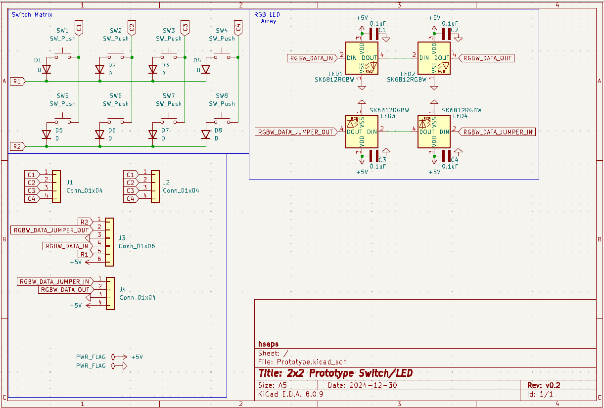
KiCad
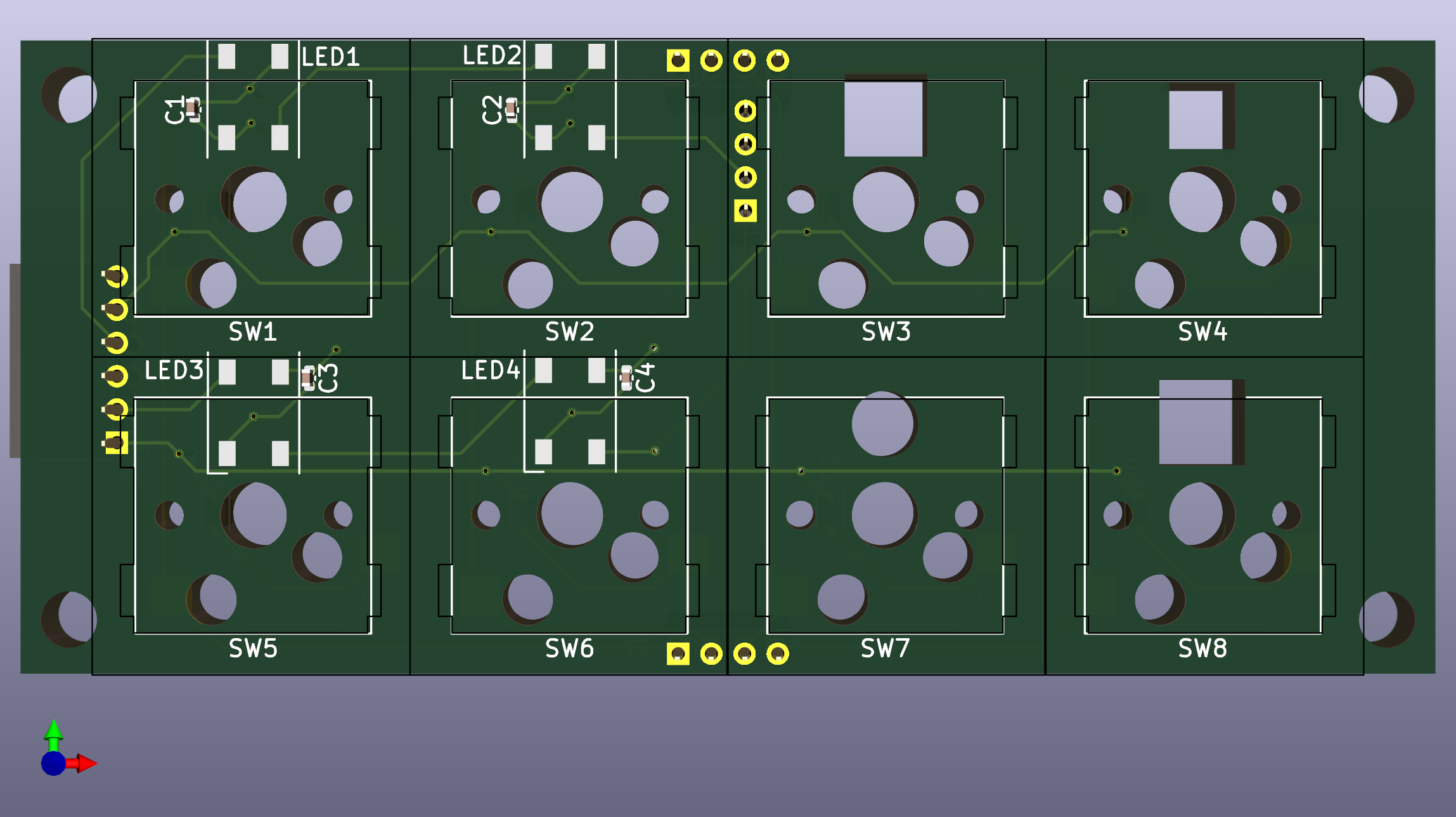
Prototype
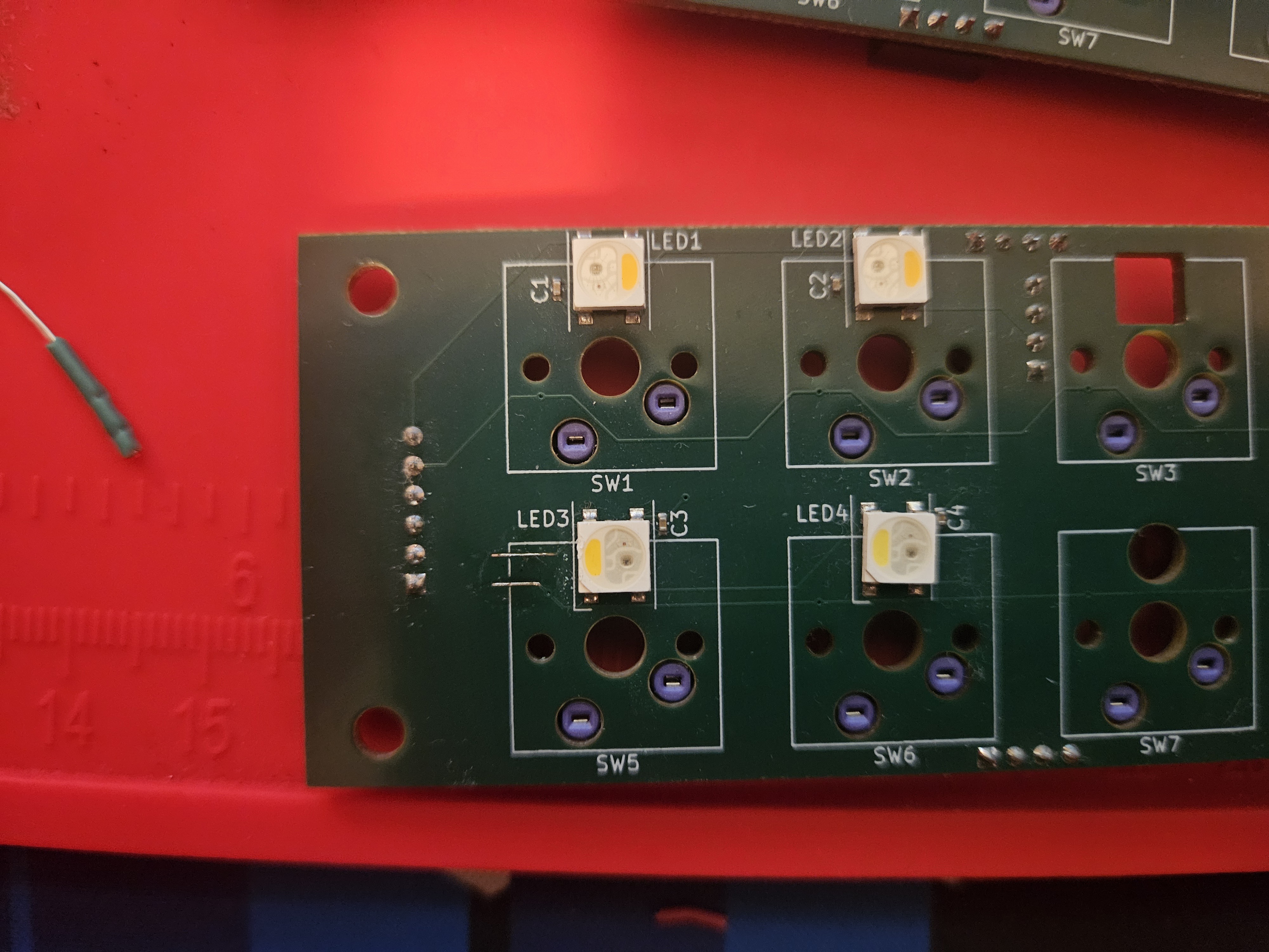
Between review and production, I managed to disconnect these traces from their respective terminals.
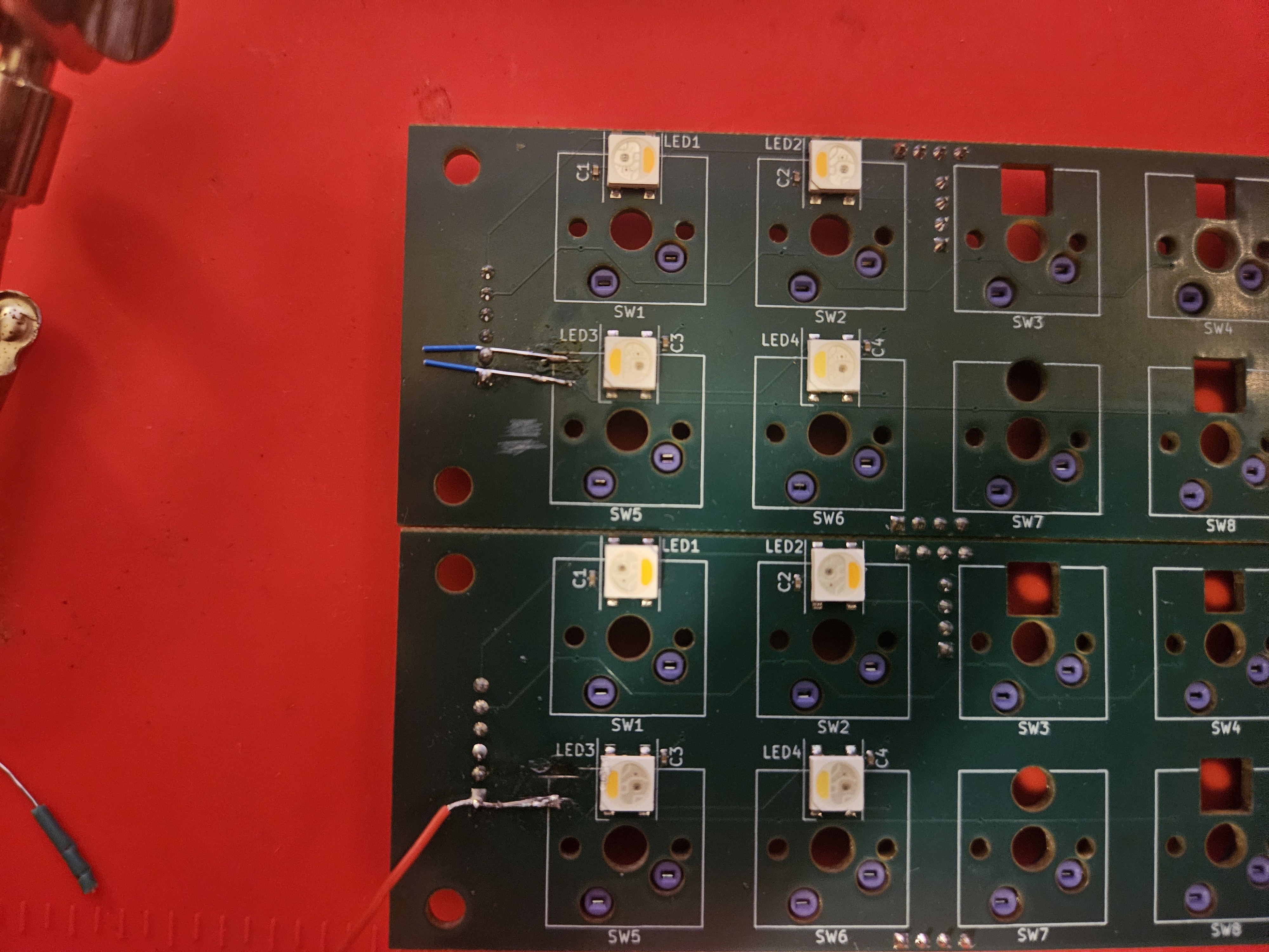
I scraped the pcb substrate to expose the traces and soldered new wires to connect the traces to the appropriate terminals
Schematics