RGBW Mechanical Keyboard
Designing a custom mechanical keyboard from the ground up.
RGBW Mechanical Keyboard
Overview
Designing a custom mechanical keyboard from the ground up.
Project Overview
This project was an attempt to solve a real world problem. I wanted a mechanical keyboard with a 65% compact, in-line layout, hot-swap mechanical switches, and most importantly, backlit with RGB-W LEDs
Key Features
KEY Features
- RGBW LEDs: RGB LEDs with a dedicated W channel for white. Cool, neutral, and warm white are all considered.
- Sensor Fusion: Uses a 5-sensor IR array for accurate line position detection
- Adaptive Speed: Automatically adjusts speed based on track curvature
Wireless Monitoring
- Real-time Telemetry: Sends sensor data and control parameters via Bluetooth
- Parameter Tuning: Live PID parameter adjustment using custom Python GUI
- Performance Logging: Records track performance for analysis and optimization
Safety Features
- Obstacle Detection: Ultrasonic sensor for collision avoidance
- Battery Management: Low voltage detection and automatic shutdown
- Emergency Stop: Wireless emergency stop functionality
Technical Specifications
| Specification | Value |
|---|---|
| Microcontroller | Arduino Uno R3 (ATmega328P) |
| Operating Voltage | 7.4V (2S LiPo) |
| Maximum Speed | 1.2 m/s |
| Line Detection Range | 12cm wide sensor array |
| Battery Life | 45 minutes continuous operation |
| Weight | 485g |
| Dimensions | 18cm x 12cm x 8cm |
Algorithm Implementation
The robot uses a weighted average algorithm to determine line position:
- Sensor Reading: Five IR sensors provide analog values (0-1023)
- Thresholding: Convert analog values to binary (line/no line)
- Position Calculation: Weighted average gives position (-2 to +2)
- PID Control: Error correction using PID algorithm
- Motor Control: Differential steering based on PID output
Data Visualization & Analysis
Real-time Performance Plots
Performance Results
After extensive testing and PID tuning, the robot achieved:
- Line Following Accuracy: 95% on standard tracks
- Maximum Track Speed: Successfully follows lines at 80cm/s
- Curve Handling: Navigates 90° turns without losing the line
- Obstacle Response: Stops within 10cm of detected obstacles
Lessons Learned
- PID Tuning: Start with proportional control only, then add integral and derivative terms
- Sensor Calibration: Regular calibration is crucial for consistent performance
- Power Management: Use voltage regulators for stable sensor readings
- Mechanical Design: Proper wheel alignment significantly improves tracking accuracy
Future Improvements
- Machine Learning: Implement adaptive PID parameters using reinforcement learning
- Multi-Line Support: Add capability to handle intersections and multiple line paths
- Wireless Communication: Upgrade to WiFi for remote monitoring and control
- Advanced Sensors: Add color sensors for enhanced track detection
Build Instructions
Assembly Instructions
Step 1: Mechanical Assembly
- 3D print the chassis using the provided STL files
- Mount the motors and wheels to the chassis
- Install the sensor array at the front of the robot
- Secure the Arduino and motor driver board
Step 2: Electronics
- Follow the circuit schematic to connect all components
- Use the custom PCB design for a cleaner installation
- Test all connections before powering on
- Upload the Arduino code and calibrate sensors
Step 3: Software Setup
- Install the Arduino IDE and required libraries
- Upload the main control code to the Arduino
- Install Python dependencies for the tuning interface
- Run initial calibration and PID tuning procedures
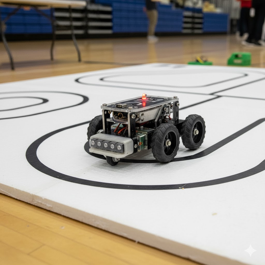
Line following robot overview
Schematics
